The Humble Homepage of Christopher Erickson
Repairing the Meade DS-Series Telescope Motors
Has your Meade DS-Series telescope been
suffering from random slewing?
Does it creep after beep?
Does it lose it's alignment without explanation?
You don't want to deal with Meade Customer Support?
I hear they are happy to send out new motors to those who ask.
Or do you want to try to fix the problem yourself?
If so, here is the information on how I fixed my DS-Series motors.
First things first, make sure you are
using the most recent version of firmware
from Meade's web site. Second, make sure that you have reset the Autostar to
remove any possibility of data memory corruption. Third, make sure you are
using good batteries or better yet, a strong external 12VDC power supply
capable of about 1.5 amps. If your problems still exist after checking these
things, you sound like a good candidate for these instructions.
First, the problem appears to be caused
by electrical noise from the motors
feeding back into the electronics of the motor control circuit and causing it
to malfunction. The
fix is to filter out that motor electrical noise. Credit for
the solution must go to Tony George, who posted his findings on Weasner's
awesome ETX web site. Here are the pictures of the motor repair process:
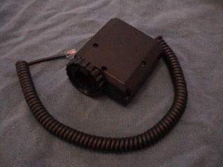
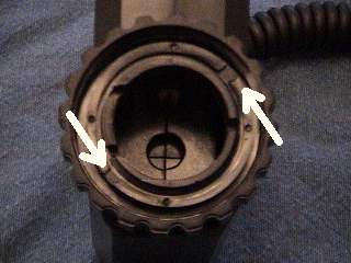
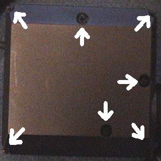
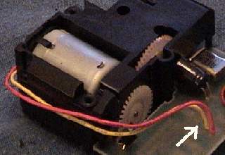
On the left is the basic motor. The
picture on the right is of the lock ring that must be
removed by rotating it in the direction of the arrows. The arrows are pointing
to
the ring notches that you will use when removing the ring and the spinning locking
nut.
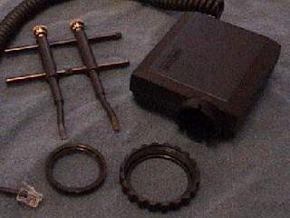
On the left you will see the motor with the
locking ring and spinning nut removed. The
spanning tool in the same picture is what I used. If you don't have a spanning
tool, a
screw driver or a pair of needlenose pliers might work for you.
The picture on the right indicates the seven screws that must be removed
next.
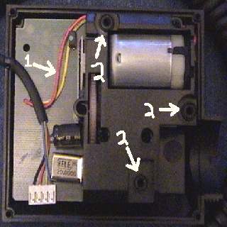
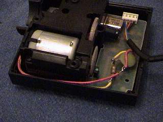
Once you have the motor opened, you will note
the motor power wires, indicated in the
left picture as item #1. In the same picture you will note the small
"O"-rings that must
not be lost or ruined. They are marked as items #2. There are six in
total. Three on
the top of the motor subassembly and three on the bottom. They are used as
shock
absorbers and meant to isolate motor vibration from the rest of the telescope to some
degree. They also help to dampen motor noise.
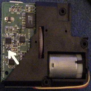
The picture on the right shows the location where the motor wires are
soldered to the
circuit board. Due to the fragility of the traces on the circuit board, it is
very easy to
damage it by trying to modify the circuit at this place. I suggest that you
don't try it.
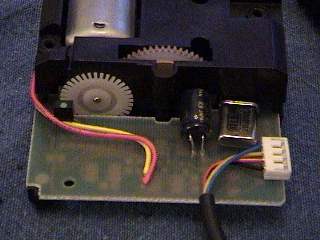
The picture on the left shows where the
action is going to take place. The first thing to
do is to CAREFULLY turn up the motor wires so they point directly up from the
circuit board, as shown in the picture on the right.
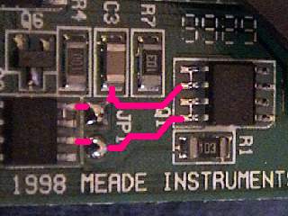
The picture on the left shows the traces that
would be severely damaged if modification
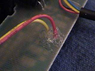
were attempted here. Don't try it! On the right, put hot-glue around the
wires as a strain
relief to prevent them from breaking off during the modification.
Once the glue hardens, you can cut and strip
the shorter wire and remove the insulation
from a short length of the longer wire, as shown in the left
picture. Removing the
insulation from the longer wire without damaging the wire is harder than it looks.
Take your time and do it right. Be careful not to tug on the wires where they
connect
to the circuit board. The hot glue strain relief isn't infallible! Using
the tip of your
soldering iron to melt/burn the insulation a bit might make it easier for you to cut
it
away.
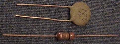
The right picture shows the two new components that you are going to add to the
motor wires. A 3-Ohm, 1/4-watt resistor and a .01mf ceramic capacitor.
Radio Shack
has the capacitors but they do not have 3-Ohm resistors. Three 10-Ohm resisters in
parallel would work, but it might be easier to check with a local electronics or stereo
repair shop first. You can also get the correct parts from Jameco Electronics.
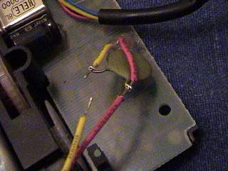
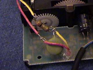
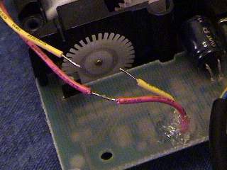
These two pictures show the installation of
the two new components into the motor wires.
In hindsite, I think that I should have connected the capacitor to the other side of
the
resistor. However it will probably work fine in either configuration. If
I wasn't so
lazy, I would re-do the modification and take a new set of pictures!
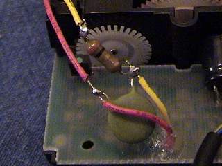
These pictures show the components soldered
in place and tucked-down in preparation
for motor reassembly. Make sure that the motor wires don't get in the way of
the gears
or the optical encoder components. Also make sure that the motor wires don't get
caught between the the case halves. Basically, reassembly is simply the reverse of
disassembly. Be careful with the six little "O"-rings. It is REAL
EASY to strip out the
thread holes of the seven case screws, so be careful there too! I have found out
that if
some of the screws don't hold too well after all of this, it probably isn't a really big
deal
because the lock ring seems to provide the majority of the strength in keeping the whole
motor assembly together.
You will need to perform an Autostar
motor recalibration after all of this, but that isn't a
big deal. You will also note that maximum-speed slewing is a tiny-bit slower than
before.
To me, that's a small sacrifice for getting the darn thing to work!
That's it!
I hope that this information is useful to
you and that you don't have any problems trying
to perform the work described here. All of the usual risk and suitability
disclaimers,
blah-blah-blah-blah, apply to this information.